 hnmindgroup

What Is a Ballistic Separator And How It Separates 2D and 3D Materials?
200Learn how a ballistic separator separates 2D, 3D and fine materials, where it fits in recycling lines, and what affects sorting performance.
View detailsThroughput, bulk density and feed conditions belong in the same conversation. Here is how to turn a production target into a useful equipment brief.
“We need to process 10 tonnes per hour. Which model should we choose?”
It is a useful starting point for an equipment enquiry. But it leaves out a question that can change the selection: how much space does that material occupy when it reaches the separator?
Ten tonnes of loose packaging and ten tonnes of a denser mixed stream can represent very different volumes. The condition of that material matters too: loose items, unopened bags and damp clumps do not present the same sorting task.
To size a ballistic separator, define the stream entering the machine, express its load in both mass and volume, and establish the separation result required at that load. The following steps turn a headline capacity into a more useful project brief.
A plant’s total intake is not automatically the load on every machine in the line.
If a trommel, manual sorting station or another upstream process removes material first, the ballistic separator receives only the remaining selected stream. Its composition may also be different from the original intake.
Mark the proposed separator inlet on the process diagram. Record the quantity and condition of material at that point. For an existing line, use measurements from that stream where available. For a new plant, identify which figures are measured and which are design estimates.
For example, suppose a plant receives 20 t/h and an assumed 45% of that mass reaches the proposed separator. The estimated separator feed is:
20 t/h × 0.45 = 9 t/h
This is a hypothetical mass-balance example, not a recommended design split. If the upstream removal rate changes, the separator load changes with it. The volume share also cannot be assumed to equal the mass share.
Mass flow describes how much material enters by weight. Volumetric flow describes how much space that material occupies. Bulk density connects the two:
Volumetric flow (m³/h) = mass flow (t/h) ÷ bulk density (t/m³)
Bulk density includes the voids between items. It is different from the density of the plastic, paper or metal itself.
Consider two hypothetical feed conditions at the same mass flow:
| Calculation input | Example A | Example B |
|---|---|---|
| Mass flow | 9 t/h | 9 t/h |
| Assumed loose bulk density | 0.15 t/m³ | 0.075 t/m³ |
| Calculated volumetric flow | 60 m³/h | 120 m³/h |
Halving the assumed density doubles the calculated volume. These values illustrate the conversion only; they are not typical density ranges or a capacity rating for a MIND machine.
When comparing a capacity expressed in m³/h with a project target in t/h, first establish a bulk density representative of the feed entering the machine. Keep the original units visible in the comparison so the conversion can be checked.
The conversion is only a first check. It does not establish separation quality, acceptable object size or mechanical loading. A calculated volume within a published rating is not, by itself, proof that a machine suits the application.
For an initial estimate, a weighed quantity and its known occupied volume can provide a bulk-density value. Record the sampling point and filling method, and repeat the measurement across representative conditions. Agree a more detailed sampling method with the equipment supplier when developing the design.
A density measured in a compacted transport load should not be used without checking whether it represents the loosened material entering the separator. Likewise, a single convenient sample should not stand in for all shifts or seasons.
An hourly average can hide a very uneven feed pattern. A loader emptying a batch into a hopper may create a different inlet load from a continuously metered conveyor, even when both deliver the same total mass over an hour.
Record the normal operating rate, the observed peak rate, the duration of peaks and the measurement interval. “Peak load” is incomplete unless the time basis is clear: a short surge and a sustained high load are different design conditions.
Daily tonnage also needs a realistic operating-time assumption. In a hypothetical project, 72 tonnes processed during eight effective feeding hours requires an average of 9 t/h. If only six hours are available for feeding, the required average becomes 12 t/h. Scheduled shift length and effective feeding time should therefore be stated separately.
Discuss the intended feed-control method alongside machine size. A larger separator does not automatically resolve an uncontrolled discharge from the equipment ahead of it. Any capacity allowance should follow the project’s measured variation and operating plan, rather than an unexplained percentage added to the average.
Two streams with the same calculated volume may still require different configurations. Include a short material description with the flow figures:
| Feed characteristic | Information to provide |
|---|---|
| Composition | Approximate shares of film, paper, rigid containers, fines and other significant materials; identify whether estimates are by mass or volume. |
| Size | Normal size range, largest expected objects and any upstream screening cut. |
| Preparation | Whether bags are opened and whether material is loose, shredded, compacted or attached to other items. |
| Moisture | Measured moisture where available, the measurement basis, and observations of wet or sticky material. |
| Difficult items | Long flexible objects, tangles, dense pieces and other material requiring a suitability check. |
| Variation | Changes by supplier, collection route, shift or season. |
Photographs and video help explain these descriptions. For an initial enquiry, show the actual proposed feed and its delivery pattern, rather than only the waste before upstream treatment.
Machine configuration is part of the assessment. Discuss the working width and length, paddle surfaces and perforations, deck inclination and infeed arrangement. These details must follow the material and the required separation result. Confirm which options are available for the proposed model.
The useful question is how much representative material a separator can process while achieving the agreed output requirements.
Ballistic separation commonly produces flat or flexible 2D material and rolling or rigid 3D material. Perforated paddles can provide a screened fine fraction. These are physical separation groups, not guarantees of individual material purity.
Define what the next process needs from each output. A film-recovery route may require a different assessment from a line preparing mixed combustible material. “Good separation” is too vague to use as a trial acceptance criterion.
For a chosen target material, distinguish two measurements:
For example, if a trial feed contains 100 kg of target material and 80 kg reaches the desired output, recovery is 80%. If that output weighs 160 kg in total, purity is 50%. These are hypothetical calculations showing why the two measures should be reported separately.
A useful trial record links the measured inlet rate to output sampling over a corresponding stable operating period, allowing for material travel time. Record machine settings, test duration, feed condition and any interruptions. Check the other outputs for lost target material and investigate unexplained differences between measured input and output mass.
A separator selection also creates requirements for the equipment around it. Review how material enters, how it is distributed, and how each output is removed.
Check the feeding conveyor or other metering equipment, the spread of material across the inlet, and the transfer into each discharge conveyor. The receiving equipment must handle the expected volume and behaviour of its own stream, including changes during normal operation.
For your project, establish the receiving capacity of each downstream route. Dividing the incoming tonnage equally between three conveyors is not a valid substitute for an expected output balance. The streams may differ substantially in both mass and occupied volume.
Check installation height, support requirements, available space and maintenance access alongside the process data. A suitable separation duty still needs a workable installation.
A practical first enquiry should contain:
Label unknown values clearly. A brief with a few explicit uncertainties is more useful than a detailed table of unsupported assumptions.
You can calculate a mass-flow equivalent using a stated bulk density. That calculation does not confirm the rating applies to your feed, configuration or required sorting quality. Ask for the conditions behind the proposed capacity.
Do not assume a linear relationship across machines or applications. Ask the supplier to explain the proposed size using the actual feed, configuration and required result. Area is one item in that assessment.
A video can reveal useful feed and handling details. On its own, it does not provide a measured flow rate, representative bulk density or verified recovery result. Use it to support the project data and plan any further testing.
A useful sizing brief connects four things: the stream entering the machine, its mass and volume, its variation over time, and the output quality required. Together, those details give a supplier a basis for explaining a model recommendation.
Planning a MIND ballistic separator installation? Include your process diagram, feed photographs or video, target throughput and available material data in your enquiry. State which values are measured and which are estimates so the proposed configuration can be assessed against your project conditions.
All numerical examples are hypothetical calculations, not model ratings or performance guarantees. Final equipment selection requires a review of the actual feed, operating conditions and agreed output quality.
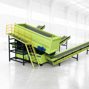
Learn how a ballistic separator separates 2D, 3D and fine materials, where it fits in recycling lines, and what affects sorting performance.
View details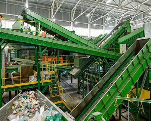
Learn when a ballistic separator and trommel screen should be used together to separate size, 2D and 3D materials in recycling lines.
View details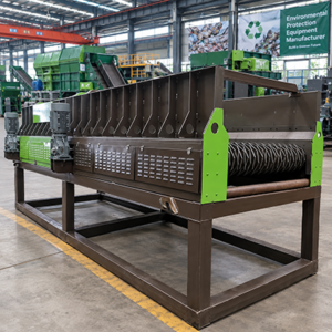
Disc screen vs trommel: compare screening efficiency, clogging and upkeep for lines. Find right star screen for your plant. Free quote from HN Mind Group.
View details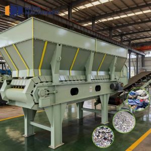
Chain plate feeder delivers steady, even feed to waste sorting lines. Robust steel build, low maintenance, adjustable speed. Get free quote from HN Mind Group.
View details